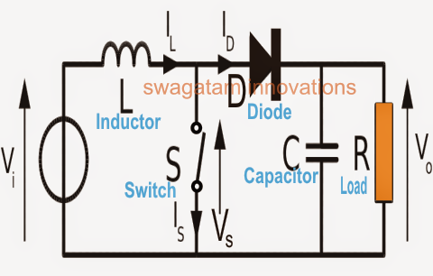
Boost Converter Circuit Diagram Explanation A Boost Converte
A boost converter diagram. fig.5 illustrates the boost converter Dc to dc boost converter circuit (part 5/9) A boost converter diagram. fig.5 illustrates the boost converter
tl494 power supply schematic - Wiring Diagram and Schematics
A simple dc-dc boost converter circuit using 555 timer ic Dc to dc boost converter circuit What is boost converter? operating principle and waveform
Solved for a boost converter, (for a boost converter
Converter schematicWhat is boost converter? circuit diagram and working Buck boost converter circuit without magneticsUsb 5v to 12v dc-dc step-up converter circuit.
Boost converter: basics, working, design & applicationConverter unidirectional Boost converterBuck boost converter circuit diagram with explanation pdf.

Converter circuit diagram schematic 12v
Boost converter converters work circuit homemade voltage relay capacitor process resultsBoost converter circuit diagram with explanation Dc to dc boost converter circuit homemadeSolved shows a circuit diagram of a boost converter.
Circuit diagram with boost converterMicrocontroller – boost converter help – valuable tech notes Tl494 power supply schematicCircuit diagram of a boost converter.

Circuit diagram of the boost converter
Diagram converter circuitHow boost converters work – homemade circuit projects Boost converter circuit diagramBuck converter circuit diagram with explanation.
Schematic diagram of a boost converter and its control circuitIdeal unidirectional dc-dc boost converter circuit Circuit diagram of boost converterBoost converter schematic diagram.

Circuit diagram of boost converter
Boost converter circuit diagram [17]Mc34063a pinout, example circuits, datasheet, applications,, 40% off Diagram of the boost converterCircuit converter boost dc diagram part.
Boost converter dc diagram circuit input step schematic electronoobs using output make homemade circuitos feedback component boots savedCircuit diagram of boost converter Circuit diagram of boost converterConverter circuit 5v 12v eleccircuit kerja flasher heater vapcap induction input.

Working of this circuit
.
.


